


JDY-23 Mạch Thu Phát Bluetooth 5.0
Thương hiệu : Khác
50,000đ


JDY-23 mạch thu phát bluetooth 5.0 có khoảng cách truyền tối đa lên đến 60m.Hỗ trợ người dùng sửa đổi tên thiết bị thông qua các lệnh AT,tốc độ Baud nhanh chóng và thuận tiện sử dụng linh hoạt.
Thông số kỹ thuật :
- Model : JDY-23
- Điện áp hoạt động :1.8~3.6VDC
- Bluetooth hỗ trợ : 5.0
- Dòng tiêu thụ khi hoạt động : 800uA
- Tần số hoạt động : 2.4Ghz
- Giao tiếp chuẩn : uart
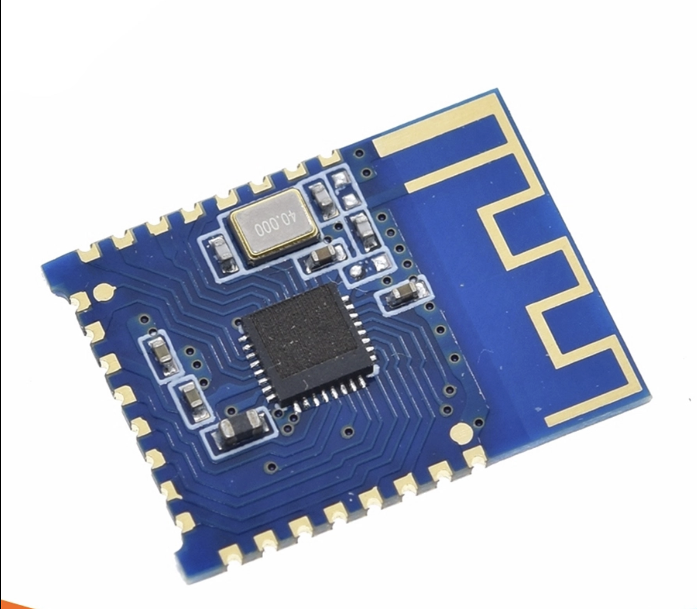
- Anten tích hợp trên mạch
- Độ nhạy : -97dBm
- Khoảng cách truyền : 60m
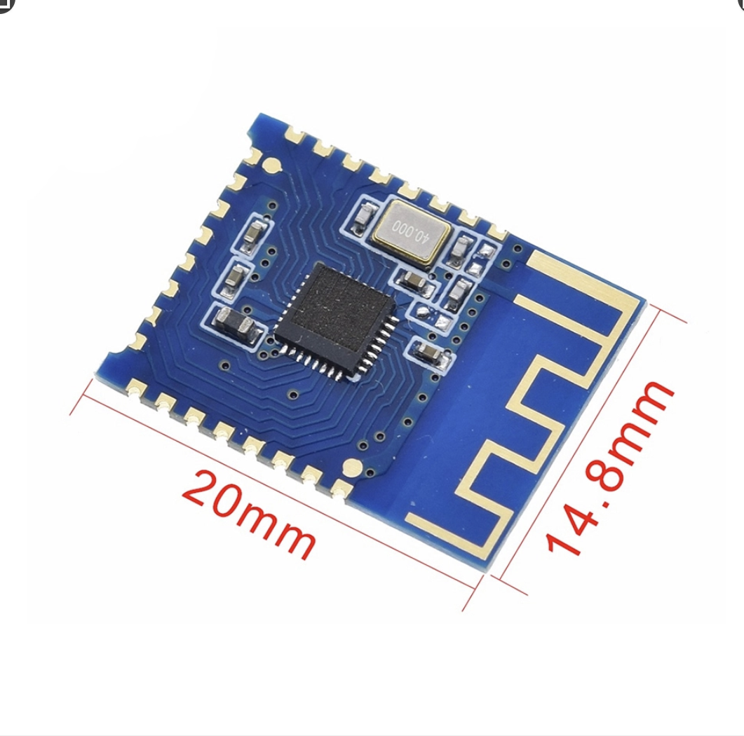
- Kích thước : 19.6x15x1.8mm
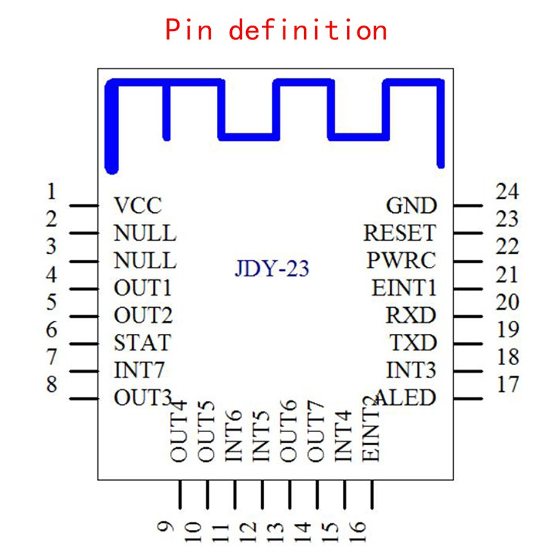
Sơ đồ chân:
Pin # | Features | Description |
1 | VCC | Power supply (1.8-3.6 V) |
2 | NULL | No |
3 | NULL | No |
4 | OUTPUT1 | IO1 output pin (high and low level control APP support) |
5 | OUTPUT2 | IO2 output pins (support APP control of high and low levers) |
6 | STAT | The status of the pin connection, connected high, not connected to low |
7 | INPUT7 / PWM4 | INPUT7 mode: For the input pin, the APP can read the status of this pin. PWM mode: PWM4 output pin, APP able to control PWM4 Pulse width The default value is: INPUT7 mode |
8 | OUTPUT3 | IO3 output pin (high and low level control APP support) |
9 | OUTPUT4 | IO4 output pin (high and low level control APP support) |
10 | OUTPUT5 | IO5 output pin (high and low level control APP support) |
11 | INPUT6 / PWM3 | INPUT6 mode: For the input pin, the APP can read the status of this pin. PWM mode: PWM3 output pin, APP able to control PWM3 Pulse width The default value is: INPUT6 mode |
12 | INPUT5 / PWM2 | INPUT5 mode: For the input pin, the APP can read The status of this pin. PWM mode: PWM2 output pin, APP able to control PWM2 Pulse width The default value is: INPUT5 mode |
13 | OUTPUT6 | IO6 output pins (high and low level control APP support) |
14 | OUTPUT7 | IO7 output pin (high and low level control APP support) |
15 | INPUT4 | For the input pin, the APP can read the status of this pin. |
16 | EINT2 | Input pin interrupt (in connected state, press to actively send IO status to APP) |
17 | ALED | Pin transmission indicator |
18 | INPUT3 / PWM1 | INPUT3 mode: For the input pin, the APP can read the state of thi pin. PWM mode: PWM1 output pin, APP able to control PWM1 Pulse width The default value is: INPUT3 mode |
19 | TXD | Serial output pin (TTL level) |
20 | RXD | Serial input pin (TTL level) |
21 | EINT1 | Input pin interrupt (in connected state, press to actively send IO status to APP) |
22 | PWRC | Sleep wake-up pin, active low In the connected state, the AT command can be pulled Low through the PWRC pin. |
23 | RTD | Reset pin, active low |
24 | GND | Power land |


