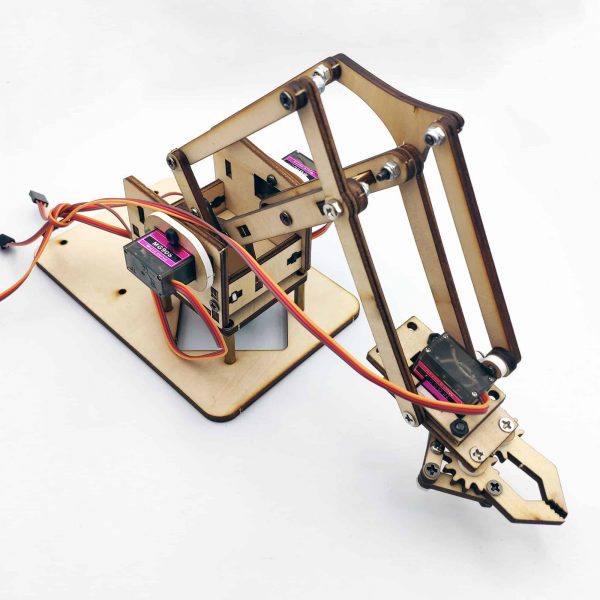
Cánh tay robot 4 servo (DIY) ( Tự lắp)
Thương hiệu : Khác
280,000đ
Bộ khung cánh tay robot 4 servo là bộ KIT cánh tay robot được cắt cnc. Bộ cánh tay robot sử dụng động cơ servo SG90 nhỏ gọn và hiệu dụng. Được sử dụng cho học tập và giảng dạy.
Chú ý: Khi lắp ráp có một số lỗ đưa vít vào bị chật thì đó không phải là do lỗ nhỏ không đúng vít mà là do thiết kế của chi tiết mặc định như thế.Quý khách chỉ cần vặn vừa đủ và không vượt quá tấm nhựa,đồng thời những lỗ như thế sẽ không cần đai ốc.
Thông số kỹ thuật:
- Chất liệu: Nhựa abs
- Ốc + vít dử dụng cho lắp ghép
- Sử dụng 4 servo SG90 để lắp ráp hoàn thiện
Hướng dẫn chi tiết lắp ráp:

step 2 :base
(1)20mm x 4
(2)9mm x 2
(3) plastic column x 4
(4) nut x 8

Screw M3*20 four

Be careful not to exceed the board, then tighten the nut below.

step 3:The first motor
NOTE:The size of the motor is very close to that of the acrylic, so the force must be slow, so as not to break the acrylic.
NOTE:The gap is the location of the line.


特别提示:木板材质孔会相对偏大,M3*8的螺丝直接锁木板上可能会偏松,建议使用M3*10或者M3*12的螺丝配合M3的螺母进行固定。其他的地方可以不用M3*10的螺丝,相互调整配合下。或者直接加点胶水固定也可以
Special tips: the hole of wood material will be too large, and M3 * 8 screws may be loose on the board directly. It is recommended to use m3 * 10、m3 * 12 screws and M3 nuts for fixation. (exchange with other positions where m3 * 10、m3 * 12 screws are used.)Or just add some glue to fix it
M3*8 screw(double)

Be careful not to tighten the screws too tightly. It will crack the acrylic board too tightly.

Step 4 :Left arm
(1)12mm x 2
(2)8mm x 3
(3) nut x 2
(4) the screw of the steering gear is one length and one shor


Screw M3*8


After power on, the motor is controlled by a rocker to turn clockwise to the end, so that the direction is consistent with the picture.

When installing a stick, add a gasket in the middle.
Yellow to the outside
Power supply 5V 2A charger

Turn to the rudder counter clockwise

Clockwise steering wheel

Step 5 :Right arm
12mm X 3
8mm x 2
6mm x 1


After power on, the steering wheel is inserted into the circuit board, turning clockwise to the same direction as the picture.

12mm x 2
6mm x 1
Nut x2


First put on the shell and then install the screws. When tightening, do not tighten too tightly.

The right arm is put on the shell first and then tightened.
Step 7: right arm + chassis
Tighten the screw and tighten the screw


Step 8: intermediate bracket
Screw the nut first


Step 9: complex with the base
The rocker moves to the right, clockwise to the end, and the steering gear is aligned with the picture

After power on, the rudder line is plugged into the circuit board, and the remote control counterclockwise turns to the end of the steering gear angle and the picture is consistent.

step 10 :Branched rod
Two screw M3*6


M3*6
M3*8

Shim(double)

step 11 : The last motor
8mm x4

The side of the mouth is large and the side is small.


4 M3*8 screws fixed


step 12 : clip
6mm x 3
8mm x 1


This step is focused on motors, the same way of operation as before. When the rocker turns left or right, the claw can be opened or closed. Finally, remember to lock the motor's screw.

Install screw M8*8 or 12
Step 13: install the clamp, the rudder is connected to the line

1234 corresponding to the position of the rudder in the next picture.


Hướng dẫn sử dụng tham khảo:
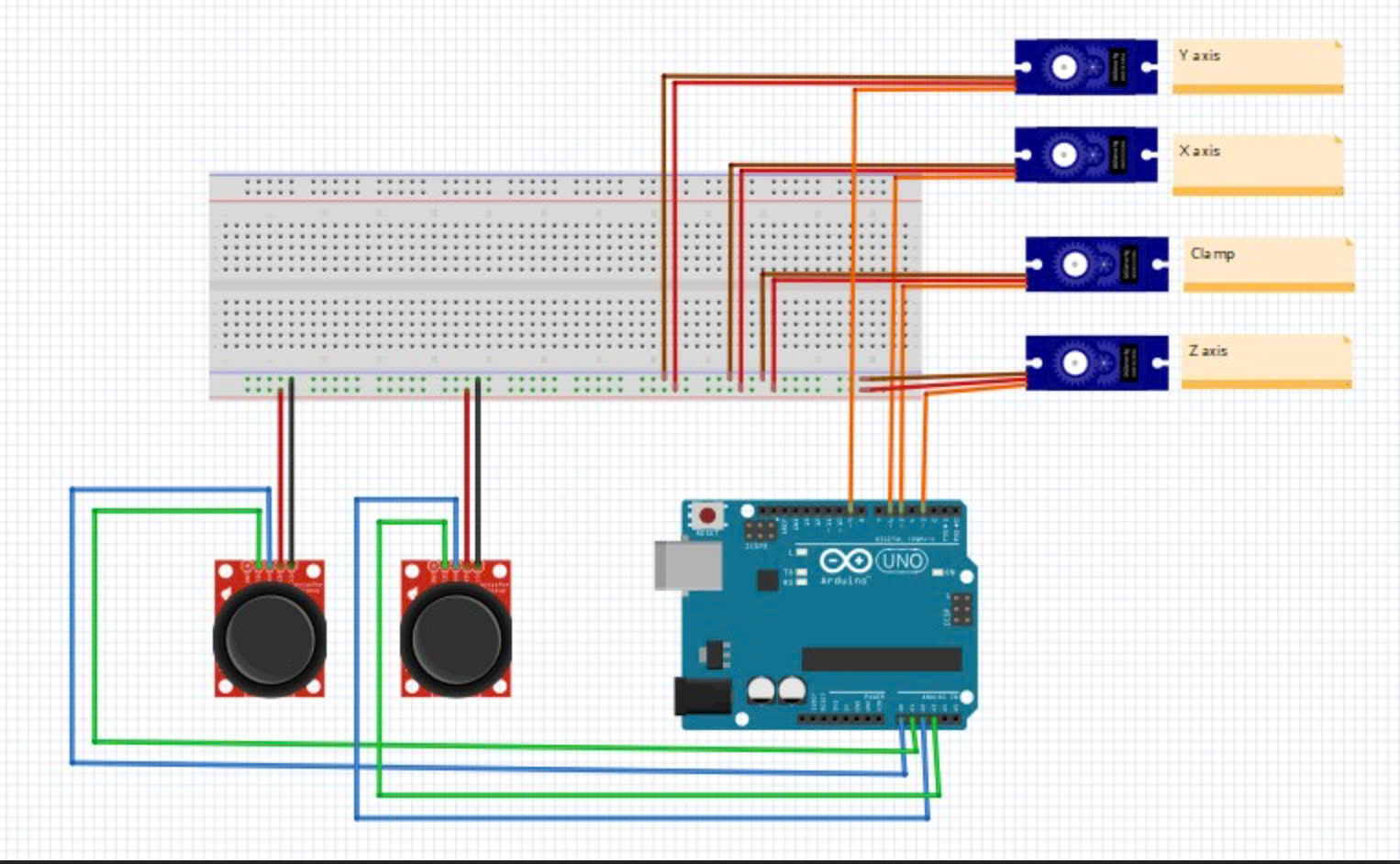
Sử dụng 2 joystick đơn kết nối với arduino uno để điều khiển 4 servo.
- Sau khi lắp ráp sản phẩm như hình tiến hành kết nối: cấp nguồn ngoài cho 4 servo, nhớ kết nối chung mass với arduino.
- Cấp nguồn cho joystick trực tiếp từ nguồn 5V arduino, chân tín hiệu của joystick và servo được kết nối với arduino.
————————————CODE THAM KHẢO—————————————
#include
Servo myservo1;
Servo myservo2;
Servo myservo3;
Servo myservo4;

int pos1=90, pos2=60, pos3=90, pos4=45;

const int right_X = A2;
const int right_Y = A5;
const int right_key = 7;

const int left_X = A3;
const int left_Y = A4;
const int left_key = 8;

int x1,y1,z1;
int x2,y2,z2;


void setup()
{

  // boot posture
  myservo1.write(pos1);
  delay(1000);
  myservo2.write(pos2);
  myservo3.write(pos3);
  myservo4.write(pos4);
  delay(1500);

  pinMode(right_key, INPUT);
  pinMode(left_key, INPUT);
  Serial.begin(9600);
}

void loop()
{
  myservo1.attach(A1);
  myservo2.attach(A0);
  myservo3.attach(6);
  myservo4.attach(9);

  x1 = analogRead(right_X);
  y1 = analogRead(right_Y);
  z1 = digitalRead(right_key);

  x2 = analogRead(left_X);
  y2 = analogRead(left_Y);
  z2 = digitalRead(left_key);
  // kẹp
  zhuazi();
  // xoay
  zhuandong();
  // servo trái
  xiaobi();
  // servo phải
  dabi();
}

//kẹp
void zhuazi()
{
    //claw
  if(x2<300)
  {
      pos4=pos4-2;

      myservo4.write(pos4);
      delay(5);
      if(pos4<45)
      {
        pos4=45;
      }
   }
  if(x2>800)
  {
      pos4=pos4+8;
      myservo4.write(pos4);
      delay(5);
      if(pos4>90)
      {
        pos4=90;
      }
  }
}
//******************************************************
 // xoay
void zhuandong()
{
  if(x1<300)
  {
    pos1=pos1-1;
    myservo1.write(pos1);
    delay(5);
    if(pos1<1)
    {
      pos1=0;
    }
  }
  if(x1>800)
  {
    pos1=pos1+1;
    myservo1.write(pos1);
    delay(5);
    if(pos1>180)
    {
      pos1=180;
    }
  }
}

//**********************************************************/
//servo trái
void xiaobi()
{
    if(y1>800)
  {
    pos2=pos2-1;
    myservo2.write(pos2);
    delay(5);
    if(pos2<15)
    {
      pos2=15;
    }
  }
  if(y1<300)
  {
    pos2=pos2+1;
    myservo2.write(pos2);
    delay(5);
    if(pos2>120)
    {
      pos2=120;
    }
  }
}

//*************************************************************/
// servo phải
void dabi()
{
    if(y2<300)
  {
    pos3=pos3+1;
    myservo3.write(pos3);
    delay(5);
    if(pos3>140)
    {
      pos3=140;
    }
  }
  if(y2>800)
  {
    pos3=pos3-1;
    myservo3.write(pos3);
    delay(5);
    if(pos3<30)
    {
      pos3=30;
    }
  }
}
Bộ khung cánh tay robot 4 servo là bộ KIT cánh tay robot được cắt cnc. Bộ cánh tay robot sử dụng động cơ servo SG90 nhỏ gọn và hiệu dụng. Được sử dụng cho học tập và giảng dạy.


